MRI Physics: Phase Contrast MR Angiography
This phase contrast MRA simulation will give you a sense of how phase contrast MRA works and how changing parameters will affect the image. For details about how Phase Contrast MRA works, see below. (Note that this simulation is a sort of rough estimate, it does not perform exactly like the MR machine.)
|
Aortic Velocity: 100 cm/s
Measured Velocity: cm/s |
How Phase Contrast Works
You may want to take some time to review Flow-Related Phenomena in MRI first, especially flow-related dephasing.
Phase-contrast MRA is an example of a non-contrast MRA technique. Remember that regular MRI uses both frequency shifts and phase shifts to record the position of protons within the slice. While frequency shifts depend on an actively applied gradient, phase shifts are 'remembered' by protons (until they dephase completely). Thus, if we can somehow 'program' protons to remember their phase related to how fast they were moving, we can read that out later to determine the velocity.
Most commonly in clinical use, we employ phase contrast MRA in a 'through-plane' technique, i.e. to measure the speed of blood flowing perpendicular to the imaging plane, and that's what we'll discuss here.
If we set up a gradient perpendicular to our plane, protons that flow into the plane from either direction will have experienced different amounts of phase shifts. Depending on how far they've traveled (really, how far they were away initially), their phase shifts will be different. Once they have arrived in the imaging plane, we can read out those phase shifts to figure out how far they went - and thus how fast they were going.
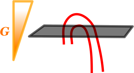
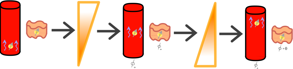
This extra phase-encoding gradient will also cause phase shifts in the non-moving parts in our slice. By using a 'biphasic' (balanced) gradient, we can 'wind' and then 'unwind' the phase. Protons that haven't moved outside of the slice will end up with a net zero phase shift - but protons that are now in a different position will experience different strengths of phase shifts forward and backwards. They will end up with a net phase shift, again proportional to how far they've traveled. The image below illustrates what happens to flowing and stationary protons, with φ representing phase.
For a more detailed explanation, see Flow-Related Dephasing.
Unfortunately, magnetic field inhomogeneities will still cause some artifacts and phase shifts for non-moving protons. Thus, phase contrast MRA uses two separate runs, one with zero phase shift and one with a positive phase shift, and then subtracts the phases from the two runs to cancel out those effects.
Aliasing
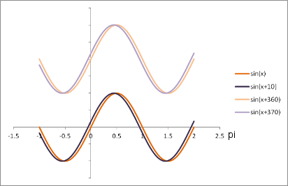
Because we are making use of phase shifts to record velocities, we are limited by the periodicity of the sine function. As you may recall, the sine function repeats itself every 2*π radians or 360 degrees. Thus, 10 degrees and 370 degrees look the same:
By selecting the strength of the gradient field, we change the amount of phase shift protons experience for a given velocity. With phase-contrast MRA, we are looking at both positive and negative velocities (i.e. velocities going up through the plane or down through the plane). Our 360 degrees are therefore split into two 180-degree chunks. The velocity that corresponds to a 180 degree phase shift is known as Venc (max velocity encoded). This is the maximum velocity the MR machine and Fourier transform can understand. Beyond that, our phase shifts are greater than 180 degrees, and the Fourier transform can't figure out if they're positive or negative. In other words, is a shift of 190 degrees +190 degrees or -170 degrees?
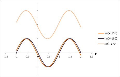
This phenomenon is referred to as aliasing, and in order to avoid it we need to set our Venc to higher than the maximum velocity in the vessel. Note that you should not set the Venc too high because the measurement error (standard deviation) is proportional to Venc. Note that the exact same phenomenon of aliasing also occurs in pulsed-wave Doppler ultrasound.
The magnitude image is usually created from the zero-shift sequence, and you can use it for anatomic localization. It is referred to as magnitude because it does not include the added phase shifts.
Some things to note in the simulation:
- The phase shift induced in moving protons causes them to be shifted in the phase-encoding direction, here the AP dimension. This is shown in the simulated middle image.
- Areas where there is no motion and little signal, like the lungs, show a lot of noise in the phase image. This is because the noise is much larger than the minimal signal, so the scanner perceives random phase shifts.
- When the Venc >> maximal velocity, there is no aliasing and the velocity measurements are pretty accurate. With Venc ~= maximal velocity, some pixels alias, so there's a little inaccuracy. When Venc < maximal velocity, there is a lot of aliasing, and the ROI can record a 0 net velocity because of mixed aliased and non-aliased pixels (remember the velocity is not uniform in the vessel). When Venc << maximal velocity, all of the pixels are aliased, and so the returned velocity is negative (opposite direction).
References
- Pelc NJ, et al. "Encoding strategies for three-direction phase-contrast MR imaging of flow." J Magn Reson Imaging. 1991 Jul-Aug;1(4):405-13.
- Hashemi, R. H., Bradley, W. G. & Lisanti, C. J. MRI: the basics. (Lippincott Williams & Wilkins, 2010).
PhaseEncSim Applet copyright 2013 Mark Hammer. All rights reserved.