MRI Physics: K-Space Trajectories
You may wish to jump to simulations of Cartesian versus radial K-space trajectories and K-space ordering in MR Angiography.
Cartesian Trajectories
Remember that MR images are acquired in K-Space, where image information is stored in the frequency domain rather than the spatial domain. Each point in K-space corresponds to a particular spatial frequency and contributes to the entire image. For a full discussion of spatial localization in MRI and why images are acquired like this, please see the page on Spatial Localization.
As a brief review, K-space is a matrix the same size as the resulting image. The points in K-space are acquired through frequency encoding and successive phase encoding steps. Once the entire matrix is filled in, the inverse Fourier transform decodes the frequency information into the actual image.
The traditional way of acquiring K-space data is through Cartesian, or rectilinear, phase and frequency encoding. This fills the K-space matrix in successive lines like so:
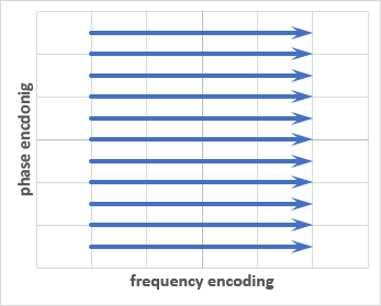
Each line of K-space is a separate phase encoding step. The phase encoding may be done in the anterior-posterior axis as in the example above, left-to-right axis, or any arbitrary axis. Remember that phase encoding is the most time-intensive aspect of MRI. Any patient or tissue motion that occurs between successive phase encoding steps will lead to artifacts in the image.
Note that even for Cartesian trajectories, the order of filling of K-space can be changed to suit the needs of the application. This is most important for MR angiography.
Radial Trajectories
There are several disadvantages of Cartesian filling. For example, the center of K-space, which corresponds to image contrast, is only acquired once. Also, each line is acquired only once and is therefore susceptible to patient motion. Finally, one must acquire enough phase encoding steps to prevent aliasing (or wrap) artifact from body parts outside the desired field of view.
One alternative to a Cartesain trajectory is radial filling, where the scanner acquires multiple radial lines (like a starburst) to fill the K-space matrix, as shown below
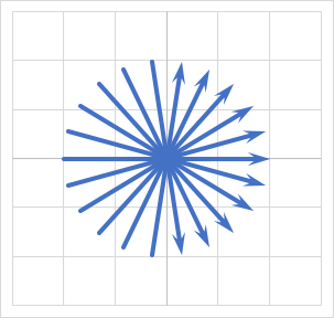
Note that a radial trajectory has no phase encoding steps. Each line in the trajectory is a frequency encoding step. Thus, there is no possibility of wrap artifact with radial trajectories. This allows small field-of-view (FOV) imaging. Also note that the center of K-space is sampled multiple times, although the peripery is relatively undersampled. This may compromise spatial resolution. However, radial sampling tends to be much less sensitive to motion artifacts. One small technical consideration to be aware of is that the radial lines that are acquired must be "gridded" or interpolated to form a standard Cartesian grid before application of the inverse Fourier transform.
|
Cartesian Left-Right Anterior-Posterior Radial |
This simulation allows you to experiement with Cartesian versus Radial K-space trajectories. This is a slice of the abdomen with simulated respiratory motion along the anterior abdominal wall.
MR Angiography
While MR angiography (MRA) uses the same types of sequences as other MR imaging applications, one important distinction is the presence and timing of contrast (well, for contrast MRA). For contrast-enhanced MRA, it is critical that imaging occur when the contrast is in the vessel of interest. Remember that the center of K-space corresponds to the contrast in the image (here we are talking about image contrast, not intravascular contrast), and the periphery of K-space corresponds to detail (resolution). Thus, we want to time imaging so that the center of K-space is acquired when the vascular contrast is in the right vessel.
As noted above, with Cartesian trajectories, the default method is to acquire lines from the 'top' of K-space to the bottom. However, we can fill the center of K-space first. This method is helpful if we need precise timing, since we can wait until the moment the intravascular contrast is in the vessel of interest, then immediately start imaging the center of K-space. The periphery of K-space can be acquired later to fill in the detail of the image without compromising on contrast opacification.
|
Image Timing: Top-To-Bottom Ordered Periphery First Center First |
This simulation shows the effects of different K-space trajectory ordering on the post-contrast phase of MR angiographic images. Note the Maki artifact with center-ordered k-space imaging if the images are acquired slightly too early.
The simulation above allows you to modify the ordering of K-space acquisition to try out different techniques. Notice that the timing of acquiring the peripher of K-space is relatively unimportant, as long as the center of K-space is acquired coinciding with the contrast bolus. Also note that if the center of K-space is acquired just slightly too early, while contrast opacifies the vessels during acquisition of more peripheral lines of K-space, you may see the so-called Maki (or "ringing") artifact. Delayed imaging will solve this problem.
Keyhole Imaging. Another important application of K-space ordering in MRA is the ability to acquire high temporal resolution time series, using the same concept that the center of k-space is the most important for intravascular contrast. If we are imaging the same tissue volume, we can assume that the periphery of K-space will not change very much, while the center of K-space will vary as contrast flows through the blood vessels. Thus, we can repeatedly sample the center of K-space while undersampling (sampling only a fraction) of the periphery of K-space at each timepoint. This technique is referred to as keyhole imaging since the center of k-space (i.e. keyhole) is the focus of the imaging. Brand name versions of this technique include TWIST (Siemens) and TRICKS (GE). By using fewer phase encoding steps at each timepoint, we can dramatically increase our temporal resolution, with a relatively small penalty of spatial resolution.
References
- Huang SY, Seethamraju RT, Hahn PF, Kirsch JE, and Guimaraes AR. "Body MR Imaging: Artifacts, k-Space, and Solutions." Radiographics. 2015 35(5).
- Maki JH, Prince MR, Londy FJ, Chenevert TL. "The effects of time varying intravascular signal intensity and k-space acquisition order on three-dimensional MR angiography image quality." J Magn Reson Imaging. 1996 Jul-Aug;6(4):642-51.
Images and Content Copyright 2014 Mark Hammer. All rights reserved.